Data Center Power Architecture Comparative Analysis

Share
Data Center Power Architecture Comparative Analysis

Traditional AC Architecture vs. Next-Generation 800 VDC Architecture


Report Notes: This report is compiled from two public technical sources:

  • Source 1: NVIDIA Technical Blog (Aug 2026), "Google, Microsoft & NVIDIA Accelerate the Transition to Low-Voltage DC" — describing the new 800 VDC power distribution architecture
  • Source 2: DataCenter Tech Sharing (Oct 2026), "Huawei Data Center Electrical Architecture In Detail" — describing the existing AC power distribution system

Date compiled: October 5, 2026


1. Background & Drivers

1.1 Industry Macro Backdrop

AI infrastructure is expanding at an unprecedented pace and power density:

Metric Data Source
Data center electricity consumption growth in 2025 +17% IEA
Of which: AI-focused facility growth +50% IEA
Projected global DC electricity by 2030 ~950 TWh (nearly doubled) IEA
Infrastructure investment required through 2040 ~$9 trillion Wood Mackenzie

1.2 Core Challenges

  • AI accelerator per-rack power density continues to rise; traditional AC distribution faces high copper usage, distribution losses, and scalability limitations
  • Suppliers must support multiple customer-specific architectures, leading to long development cycles, high costs, and industry fragmentation
  • Data center power reliability requirements are extremely demanding — architecture upgrades must simultaneously ensure safety and maintainability

1.3 Two Perspectives

Dimension Traditional AC Architecture (Huawei perspective) Next-Gen DC Architecture (Google/MS/NVIDIA perspective)
Position Mature solution currently deployed at scale Future direction for high-density AI workloads
Core product FusionPower / PowerPOD OCP 800 VDC open standard
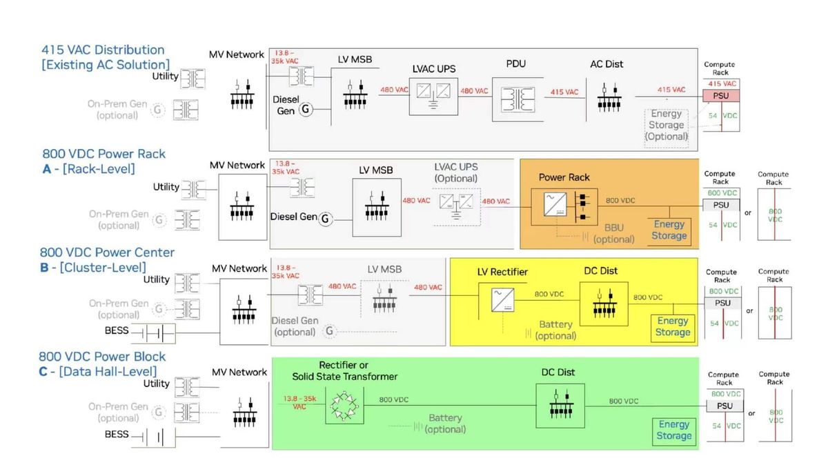
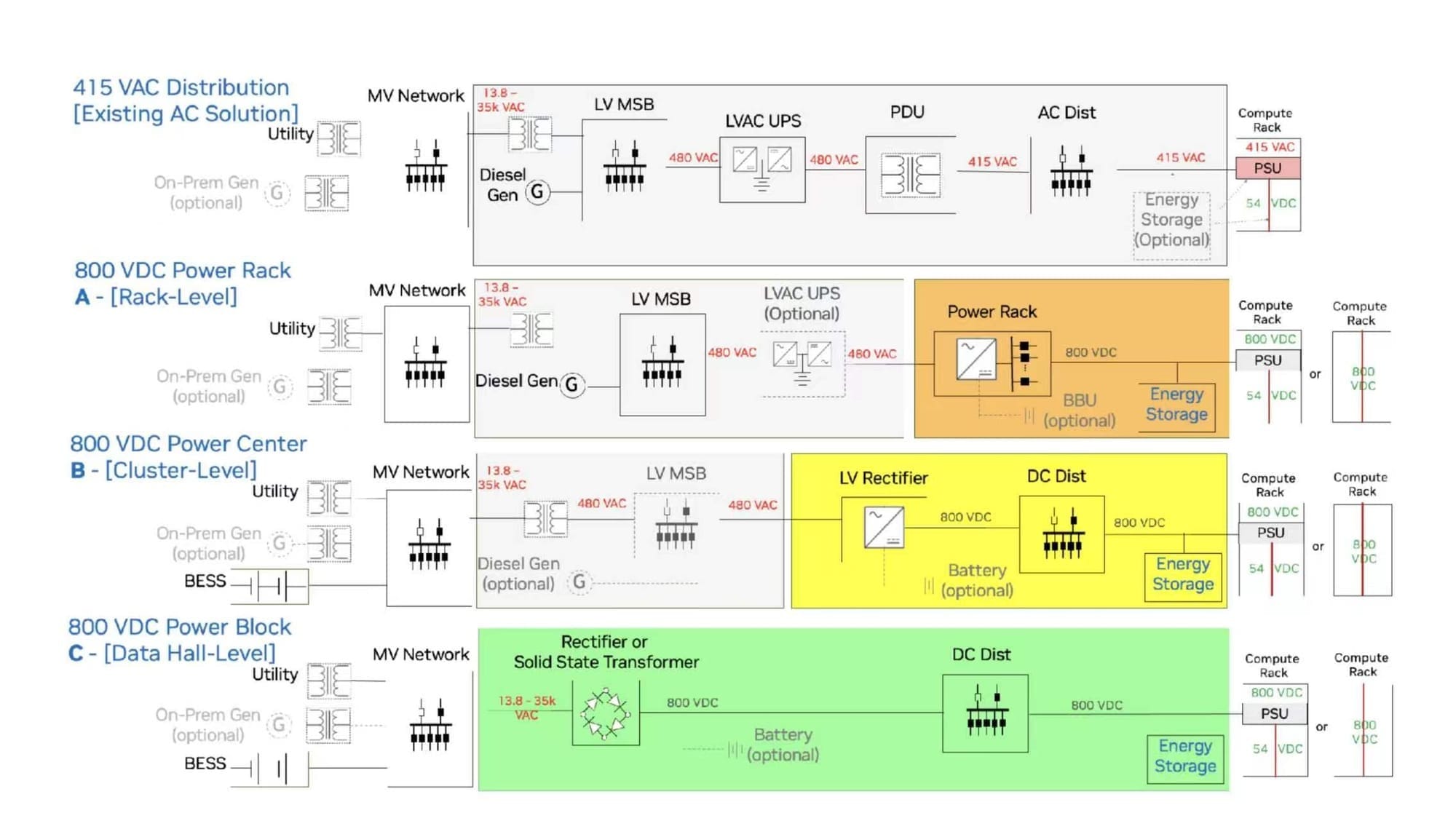
Distribution method MVAC → transformer → 480VAC → UPS → IT MVAC → 800VDC direct → IT
Industry status In mass production, widely deployed Standard under development, 80+ partners engaged

2. Architecture Comparison

2.1 Huawei AC Architecture — Seven-Layer Model

+-------------------------------------------------------------------+
|  Power Source    Utility + Diesel Generator + MV Distribution     |
+-------------------------------------------------------------------+
|  Conversion      Transformer (MV → 480VAC) + LV Distribution      |
+-------------------------------------------------------------------+
|  Protection      UPS (Modular) + SmartLi Li-ion Battery + Bypass  |
+-------------------------------------------------------------------+
|  Distribution    PDU / RPP / Busway                               |
+-------------------------------------------------------------------+
|  Load            Servers / Storage / Network + Cooling Systems    |
+-------------------------------------------------------------------+
|  Monitoring      DCIM / Power Monitoring / Alarms                 |
+-------------------------------------------------------------------+
|  Reliability     2N / DR / N+R Redundancy Architectures           |
+-------------------------------------------------------------------+

2.2 OCP 800 VDC Architecture — Two Deployment Paths

Path A: Side Power Rack (Fast Upgrade)     Path B: Direct MVAC → 800 VDC (Long-Term)
+------------------+                       +------------------------+
|  Existing 480VAC |                       |  Medium Voltage AC     |
|       |          |                       |       |                |
|  Side Power Rack |                       |  Transformer Rectifier |
|  (+/-400V /      |                       |  / SST                |
|   0-800VDC)      |                       |       |                |
|       |          |                       |  800 VDC Backbone     |
|  Compute Racks   |                       |       |                |
|                  |                       |  Data Hall DC Dist.   |
|                  |                       |       |                |
|                  |                       |  Compute Racks        |
|                  |                       |  + BESS / DC UPS      |
|                  |                       |  + DC Microgrid       |
+------------------+                       +------------------------+
  No upstream changes                      Eliminates intermediate AC
  Fastest upgrade path                     High efficiency, high resiliency

2.3 Power Transmission Path Comparison

Stage Huawei AC Architecture OCP 800 VDC Architecture
Utility input MVAC MVAC
Transform/Rectify Transformer → 480VAC Transformer Rectifier / SST → 800VDC
Distribution voltage 480VAC 800VDC
UPS form AC UPS (modular) DC UPS (optional)
Energy storage SmartLi Li-ion battery (on UPS DC bus) BESS (DC-coupled)
Rack-level distribution PDU / RPP / Busway (AC) DC busbar / DC-DC converters
Server power supply AC PSU DC PSU (requires adaptation)
Conversion stages AC→DC→AC→DC (multiple) AC→DC (single, reduced losses)

3. Redundancy & Reliability Design Comparison

3.1 Huawei AC Architecture Redundancy Schemes

Architecture Principle Characteristics
2N A/B dual independent paths, each carrying 100% load Highest reliability, highest cost, requires electrical independence
DR Distributed redundancy, 4N DR as example Flexible and scalable, modular distributed configuration
N+R N required modules + R redundant (e.g., 3+1) Balanced cost and reliability, commonly used in engineering

Key design principles:

  • A/B paths must avoid sharing critical equipment (common-mode failure risk)
  • Dual-path cables/busways require physical isolation and fire separation
  • Servers must have dual power supplies connected to A/B separately
  • IT load and cooling load are powered separately

3.2 OCP 800 VDC Architecture Reliability Design

Aspect Measure
Safety engineering Integrated from initial design; draws on EV and industrial power experience
Protection devices Solid-state breakers (millisecond-level fault clearing)
Energy storage backup BESS DC-coupled, reduced AC/DC conversion
Power resiliency DC UPS + DC microgrid
Standardization UL Solutions / NFPA / IEEE / IEC safety certifications
Interface unification OCP open specification, supplier interoperability assurance

3.3 Reliability Design Philosophy Differences

Dimension Huawei AC Architecture OCP 800 VDC Architecture
Redundancy granularity System-level / module-level (2N/DR/N+R) Device-level + system-level (solid-state breaker + BESS)
Fault isolation Traditional breakers + protection coordination Solid-state breakers (millisecond-level)
Energy storage integration UPS DC bus (requires AC/DC conversion) DC-coupled (reduced conversion losses)
Standardization level Vendor-proprietary (Huawei FusionPower) OCP open standard (cross-vendor interoperability)
Evolution strategy Mature solution, incremental optimization New architecture, safety embedded from design phase

4. Key Technology & Product Comparison

4.1 Core Equipment Mapping

Function Huawei AC Solution OCP 800 VDC Solution
Transform/Rectify Traditional transformer Transformer Rectifier / Solid-State Transformer (SST v0.3)
UPS FusionPower modular UPS (100kW/3U) DC UPS (optional integrated)
Battery SmartLi Li-ion battery BESS (DC-coupled)
Distribution PDU / RPP / Busway (AC) DC busbar / DC-DC converters
Generator Diesel generator + ATS switching Compatible (as MVAC backup source)
Monitoring DCIM + power monitoring OCP monitoring standard (to be unified)
Integration FusionPower / PowerPOD integrated cabinet Modular power block (MW-scale)

4.2 Solid-State Transformer (SST) vs. Traditional Transformer

Dimension Traditional Transformer Solid-State Transformer (SST)
Working principle Electromagnetic induction Power electronics conversion
Size/Weight Larger Smaller and lighter
Efficiency High at full load, drops at light load High across wide load range
Functionality Voltage transformation only Voltage transformation + power conditioning + protection
Response speed Milliseconds to seconds Microseconds to milliseconds
Cost Mature, low Higher (decreases with scale)
Standard Mature OCP SST v0.3 (under development)

5. Industry Ecosystem Comparison

5.1 Huawei Ecosystem

Aspect Status
Product maturity In mass production, widely deployed
Architecture model Vendor-integrated solution (FusionPower/PowerPOD)
Customization level High, configured per project
Collaboration model Huawei-led, supply chain supports
Applicable scenarios Traditional data centers, enterprise DCs, colocation DCs

5.2 OCP 800 VDC Ecosystem

Aspect Status
Product maturity Standard under development, some products delivered
Architecture model OCP open standard, cross-vendor interoperability
Customization level Low, unified interfaces reduce customization needs
Collaboration model Google/MS/NVIDIA joint, 80+ partners
Applicable scenarios AI factories, high-density AI clusters
Partner types Power rack vendors, busbar/connector suppliers, DC-DC conversion specialists, facility-level power equipment vendors

6. Evolution Path Analysis

6.1 Core Principle

OCP explicitly states: 800 VDC is not intended to replace existing AC infrastructure. It provides an additional option that can coexist with AC systems, supporting gradual transition.

6.2 Evolution Phases

Phase 1 (Current)              Phase 2 (Transition)          Phase 3 (Long-Term)
+------------------+          +------------------+          +------------------+
| Traditional AC   |          | AC + DC Hybrid   |          | DC-Native Arch.  |
| 480VAC Dist.     |  --->>  | Side Power Rack  |  --->>  | MVAC -> 800VDC   |
| AC UPS           |          | +/-400V/800VDC   |          | Direct to Hall   |
| Modular UPS      |          | Coexistence      |          | BESS/Microgrid   |
+------------------+          +------------------+          +------------------+
  Huawei FusionPower           Mt Diablo Spec                OCP SST v0.3
  PowerPOD                     Mt Diablo 2.0                Full ecosystem ready

6.3 Impact on Data Center Operators

Impact Dimension Description
Upgrade cost Path A (side rack) requires no upstream changes, low investment barrier; Path B requires distribution rebuild, high investment
Supply chain Unified standards enable OEM "build once, deploy everywhere," reducing costs
Safety compliance UL/NFPA/IEEE/IEC certification required as deployment prerequisite
Talent/skills Operations teams need to master DC distribution, solid-state breakers, and other new technologies
Compatibility Need to verify adaptation solutions for AC PSU servers with DC power supply

7. Comprehensive Comparison Summary

Comparison Dimension Huawei AC Architecture OCP 800 VDC Architecture
Distribution voltage 480 VAC 800 VDC
Conversion stages Multiple AC<->DC Minimal (single AC→DC)
Copper usage Higher (low voltage, high current) Lower (high voltage, low current)
Efficiency Impacted by multiple conversions Reduced conversion losses
Energy storage integration Requires AC/DC conversion DC-coupled, high efficiency
Redundancy architecture 2N / DR / N+R Solid-state breakers + BESS + DC UPS
Standardization Vendor-proprietary OCP open standard
Interoperability Limited High (cross-vendor)
Product maturity In mass production Standard under development
Applicable scenarios Traditional + AI data centers High-density AI factories
Upgrade path Integrated optimization Side rack → direct DC
Safety certification Mature In progress (UL/NFPA/IEEE/IEC)
Industry collaboration Huawei-led 80+ partners, tri-party joint
Representative spec FusionPower6000 OCP SST v0.3 / Mt Diablo

8. Key Conclusions

8.1 Architecture Positioning

  • Huawei AC Architecture: Represents the mature engineering practice of current data center power systems. It has formed a complete product system in reliability design (2N/DR/N+R), integration (FusionPower/PowerPOD), modular UPS, and Li-ion battery energy storage. It is suitable for current large-scale data center construction.
  • OCP 800 VDC Architecture: Represents the future direction for high-density AI workloads. It reduces copper usage and conversion losses through higher-voltage DC distribution, and drives industry collaboration through open standards. The goal is to make AI factory power "safe, interoperable, and fast to deploy."

8.2 Not a Replacement Relationship

OCP explicitly states that 800 VDC coexists with existing AC architecture, providing gradual upgrade options:

  • Short-term: Side power rack (Path A) can achieve DC power supply without modifying upstream infrastructure
  • Long-term: New AI factories can directly adopt MVAC→800VDC (Path B)

8.3 Trend Assessment

Trend Assessment
AI power density Continuing to rise, driving distribution architecture transformation
Industry standardization Moving from fragmentation to open unification (OCP-led)
DC transition Gradually shifting from "optional" to "necessary," but transition period will be long
Solid-State Transformer Key enabling technology, spec has reached v0.3
Energy storage DC coupling BESS DC integration will become mainstream
Industry investment Trillion-dollar infrastructure investment; open standards can accelerate deployment

8.4 Industry Implications

  1. Suppliers: Should participate in OCP standards early to reduce the burden of maintaining multiple customer-specific architectures
  2. Operators: New AI data centers should evaluate 800 VDC solutions; existing facilities can consider side rack transition
  3. Equipment vendors: Solid-state transformers, DC-DC converters, DC breakers represent new market opportunities
  4. Safety & compliance: DC distribution safety certification and operations standards need accelerated development

Appendix: Glossary of Key Terms

Term Full Name Description
LVDC Low Voltage Direct Current Low-voltage DC power distribution
MVAC Medium Voltage AC Medium-voltage alternating current
800 VDC 800 Volt DC Next-gen AI data center DC distribution voltage
SST Solid-State Transformer Solid-state transformer (power electronics conversion)
BESS Battery Energy Storage System Battery energy storage system
DC UPS DC Uninterruptible Power Supply DC uninterruptible power supply
OCP Open Compute Project Open Compute Project (industry consortium)
PDU Power Distribution Unit Power distribution unit
RPP Remote Power Panel Remote power panel
PSU Power Supply Unit Server power supply module
DCIM Data Center Infrastructure Management Data center infrastructure management system
SOC State of Charge Battery state of charge
SOH State of Health Battery state of health
ATS Automatic Transfer Switch Automatic transfer switch
BMS Battery Management System Battery management system
2N — Dual independent power path redundancy
DR Distributed Redundancy Distributed redundancy architecture
N+R — N required modules + R redundant modules

This report is compiled from public technical materials for technical reference only. Specific product parameters and engineering designs should be based on vendor official technical manuals and project-approved documents.